 2026-09-02
Direct answer: A casement bay window should be designed as one projecting assembly, not three unrelated windows. Coordinate the bay angle, center unit, operating flankers, handing, structural support, joining posts, head and seat drainage, screens, hardware, and service access before approving fabrication.
A Casement Bay Window Is One Projecting Assembly
A casement bay window is a projecting multi-unit window in which one or more side units, often called flankers, use casement operation. The center may be fixed or operable depending on the engineered system. “Bay” describes the projection and geometry; “casement” identifies how a sash opens. Neither word defines the support method, angle, performance rating, or allowable size.
Begin with the architectural objective. Record whether the bay is meant to increase daylight, create a wider view, form an interior seat or shelf, add ventilation, match an existing facade, or serve several of those goals. Then draw the wall opening, exterior projection, center unit, flankers, joining posts, roof or head treatment, seat board or sill, trim, interior use, and nearby circulation.
Common angles such as 30 or 45 degrees appear in manufacturer systems, but they are not interchangeable defaults. Andersen’s manufacturer-specific 30- and 45-degree bay installation guide illustrates how projection, support, joining, and installation vary within one product family. Use such documents only for the named system; do not copy a dimension or support detail into another manufacturer’s assembly.
| Decision | Record on the drawings | Failure prevented |
|---|---|---|
| Geometry | Overall width, angle, projection, unit widths, wall depth | Interior or exterior dimensions that cannot both be achieved |
| Operation | Fixed/operable status, hinge jamb, view direction, maximum travel | Reversed handing or clashing sashes |
| Support | Header, cables, braces, cantilever, posts, attachment points | Unassigned gravity or wind-load path |
| Envelope | Head, roof, corners, seat, sill, flashing, insulation, sealant | Discontinuous drainage or air seal |
| Use and service | Seat, shades, screens, hardware reach, cleaning path | An attractive bay that cannot be operated or maintained |
Compare the proposal with Forge Windows’ casement styles and layout guide, but keep the bay’s projecting geometry as a separate approval layer. A flat three-lite combination and a bay can share a visual rhythm while having very different structure and weather exposure.

Choose Operating Flankers and Handing
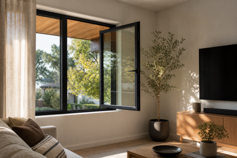
Operating flankers can provide ventilation while leaving a broad center view, but their hinge sides should not be selected from a generic left/right label. State the viewing position on every drawing, mark the hinge jamb, show the sash swing, and verify the operator location. If two flankers open toward or away from the center, compare the resulting airflow, exterior clearance, screen removal, and cleaning access.
Draw every moving part in context. Outside, check roof edges, masonry returns, siding, downspouts, shrubs, railings, walkways, adjacent windows, and the other flanker. Inside, check the bay seat, cushions, plants, shades, curtains, trim, handles, locks, screens, and furniture. A sash that can open 10 degrees is not proven suitable if the intended ventilation or required opening depends on wider travel.
Use Forge Windows’ fixed-mullion and French-pair comparison to understand how meeting conditions affect operation, but do not assume a bay flanker pair behaves like two sashes in one flat frame. Joining posts and bay angles change the line of sight, hardware clearances, and load path.
Screens usually sit on the room side of outward-opening casements. Verify that each screen can be removed without dismantling shades or the bay seat. Confirm that the lock and operator remain reachable from the intended standing or seated position. If accessibility is a project requirement, the responsible designer should review applicable reach and operating-force criteria rather than applying a residential rule of thumb.
Coordinate Structure Above and Below
A projecting bay creates gravity, wind, and movement demands that must reach the building structure. The selected system may use a designed header or soffit connection, cable support, knee braces, cantilevered framing, posts, a foundation, or another engineered arrangement. The acceptable method depends on the product instructions, opening, wall construction, loads, projection, site, and local code.
Do not ask the window supplier alone to approve the building load path unless that responsibility is explicitly within its professional scope. A qualified structural designer should verify the supporting wall, header, framing above and below, attachment points, fasteners, and temporary support during removal or installation. Existing bays deserve particular caution because an old frame, trim, or concealed member may be carrying loads not visible during a preliminary survey.
For technical comparison, Loewen’s bow, bay, and corner-window resources separate framing measurements and air, water, and structural-performance information by configuration. That manufacturer library is useful evidence of why a system-specific submittal matters; it is not a universal engineering table.
Record who designs each support component, who verifies the existing structure, who supplies anchors or cables, who inspects concealed work, and who can authorize a field change. If the opening or substrate differs from the approved survey, stop and document the condition before trimming a frame or improvising support.
Detail Air, Water, and Thermal Continuity
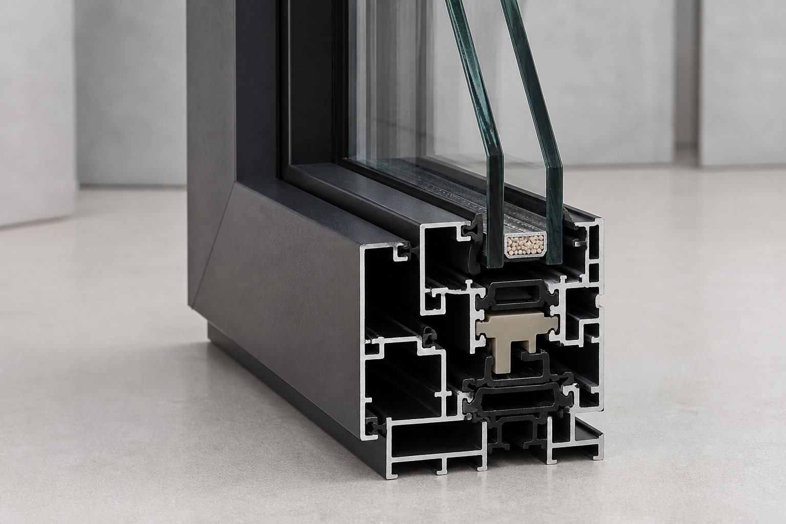
The bay interrupts a flat wall and adds corners, horizontal surfaces, joints, and exterior exposure. Draw how the roof or head sheds water, how end dams and flashing direct incidental water outward, how the seat or sill is supported and drained, and how side transitions connect to the wall’s weather-resistive barrier or other water-control layer. Keep sealant joints accessible and correctly sized with compatible backer materials.
Trace the interior air-control layer continuously around the perimeter and across assembly joints. Show insulation at the head, seat, and side transitions without blocking drainage. Address thermal bridges through support members, joining posts, metal covers, and interior finishes. A thermally broken flanker cannot compensate for an uninsulated seat board or an air leak at the bay-to-wall joint.
The Forge Windows water-managed installation sequence explains the general order of opening preparation, sill drainage, placement, flashing, perimeter sealing, and verification. The bay manufacturer’s installation instructions and the project envelope details must extend that sequence across the projecting assembly.
Performance documents must match the exact proposal. The National Fenestration Rating Council’s residential certification program explains whole-product ratings and configuration-specific certification. Confirm whether the submitted values cover the complete bay, individual component units, or another tested or simulated configuration. Label the scope rather than presenting a standalone flanker value as proof of the entire assembly.
Build a Casement Bay Approval Matrix
Use one matrix that follows the bay from design through closeout:
- Survey. Photograph inside and outside; record wall opening, depth, squareness, adjacent finishes, structure observations, obstructions, and access.
- Define geometry. Approve overall size, projection, angle, center and flanker widths, head and seat elevations, and interior use.
- Assign operation. Mark fixed and operable units, hinge sides, view direction, hardware, screens, maximum travel, and service path.
- Engineer support. Name the support method, attachment points, responsible designer, temporary support, and inspection hold points.
- Coordinate the envelope. Approve head or roof, sill or seat, side transitions, flashing, drainage, air seal, insulation, and exterior joints.
- Match evidence. Link ratings, glass, frame, finishes, hardware, and installation instructions to the exact configuration.
- Verify installed work. Record concealed conditions, support, flashing, final operation, water-management details, and closeout documents.
Keep substitutions visible. A change in center-unit width can alter projection, flanker angle, support reactions, seat dimensions, and interior sightlines. A hardware change can alter reach or screen removal. Require a coordinated revised drawing instead of approving each change in isolation.
For preliminary product questions, the Forge Windows casement specification guide identifies common frame, glass, hardware, and performance fields. Add the bay-specific geometry and responsibility matrix before requesting fabrication approval.
Frequently Asked Questions
Are the side windows in a bay always casements?
No. Bay assemblies can use fixed or operable units in several combinations. When flankers are casements, document each hinge side, operator, screen, opening travel, size limit, and clearance for the exact system.
Can a bay window support itself?
Do not assume so. The approved system needs a documented load path through manufacturer-required support and the building structure. A qualified designer should verify the header, cables, braces, cantilever, posts, foundation, anchors, and existing conditions as applicable.
Do bay-window ratings equal the flanker ratings?
Not automatically. Confirm whether each submitted rating applies to the complete bay, an individual unit, or another documented configuration. Keep the certification scope and exact product identifiers with the approved submittal.
Which way should casement bay flankers open?
Choose handing from the stated viewing position, exterior obstacles, other sash travel, wind exposure, intended airflow, screen removal, cleaning access, hardware reach, and the manufacturer’s available configuration. There is no universal left-right answer.
Conclusion: Approve the Bay as a System
A casement bay window succeeds when projection, operating flankers, support, joining, drainage, thermal continuity, and daily use are coordinated on the same drawings. Do not approve the attractive elevation while leaving the load path or corner details unresolved. Send Forge Windows the surveyed opening, plan, elevation, section, intended operation, performance requirements, support concept, wall details, finishes, and responsible design contacts for a project-specific review.